-
|
R/C
Model airplane
page_
|
 |
 |
|
| ______________________________________________________________________
BUI
BINH THO MD
__- |
|
|
|
R/CModel airplanepage My
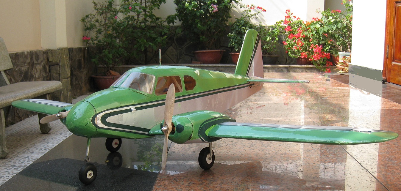
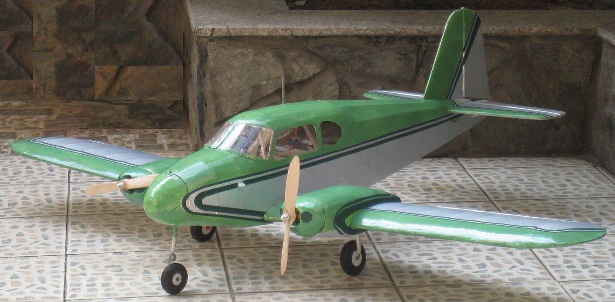
Super Piper PA 23 Apache |
|
Crete : March 2024 |
 |
|
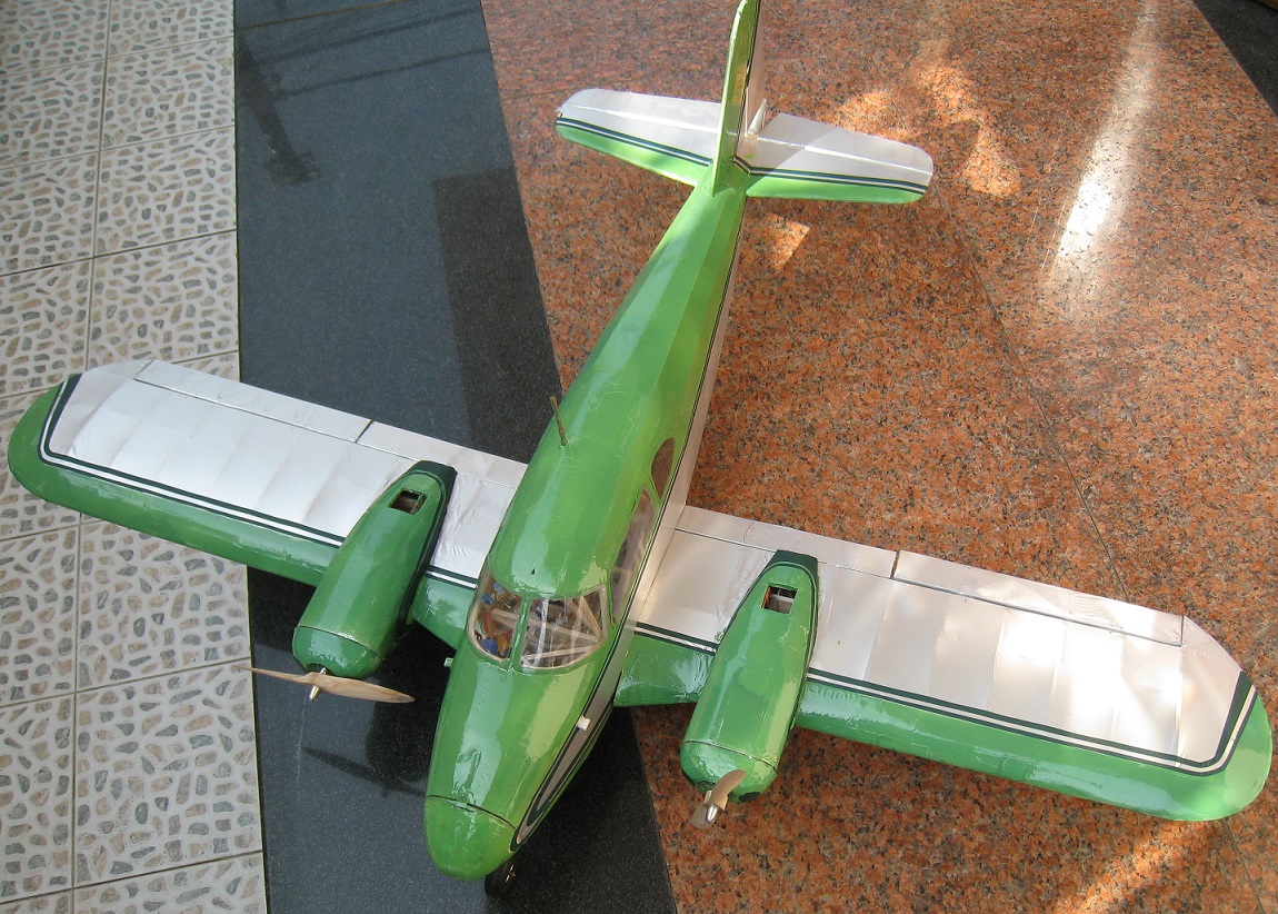
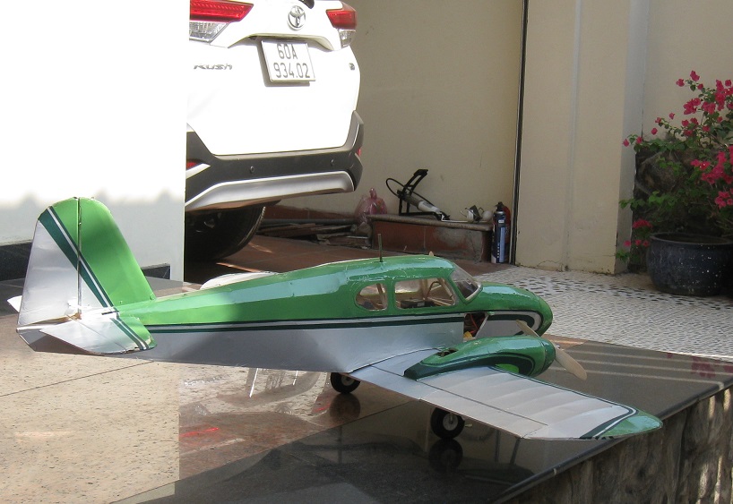
SuperPiper PA 23 Apache
| Wingspan
: 56 inch ( 1400mm ) |
| Length
: 41 inch ( 1050mm ) |
|
Low wing air foil NACA 3413 |
| Weight
: 2,8 lbs ( 1,4kg ) |
| Engine :Two
bruhsless motor 2200kv , 3s lipopolymer 2500mAh , 45C |
| Contruction :
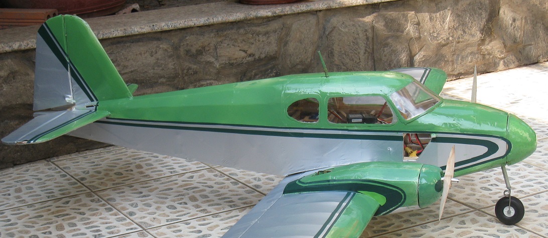
All wood air frame & thin layer silver PVC covered |
| Radio :
5 channel - 6 Miniservos . |
|
|
| On
March I decided to build an low wing electric model
bi-engine airplane , the Super Piper PA 23 Apache , the most used aircraft in
US in 60 -70 th . I used the Piper PA 23 Apache 3D view plan with some modified on the wing span
, the surface , and the horrizontal
stabilizer . More light , strong material has
been used to contruct
this model airplane ;but the balsa wood is usually the good materiel to
made its . The contruction of this aiplane is all balsa wooden
air-frame renforced by hard wood; covered by thin
light silver PVC . I thing this is the one in lightest
wooden R/C electric model airplane which I was
doing ( try on ! ) .
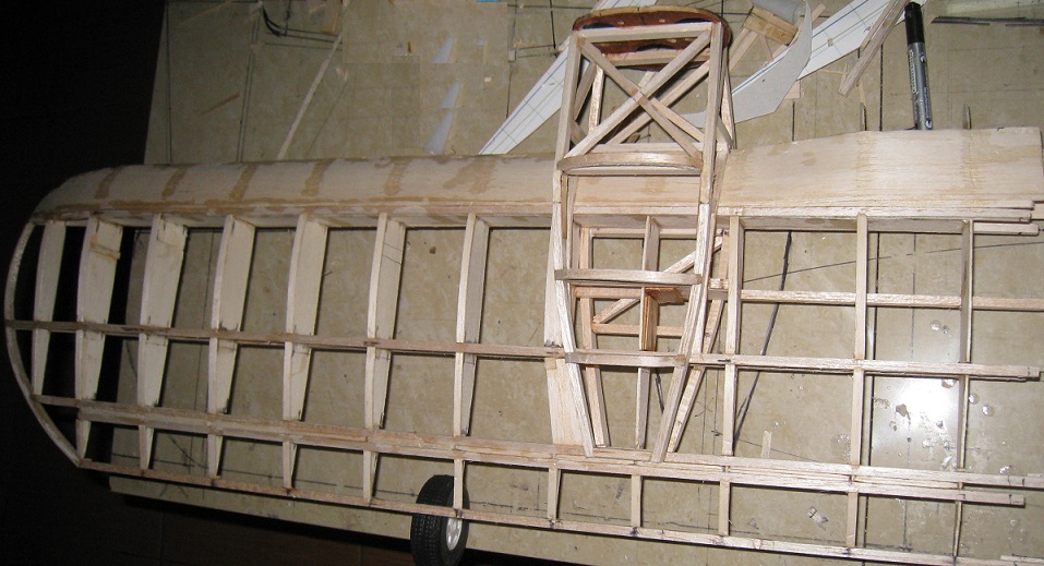
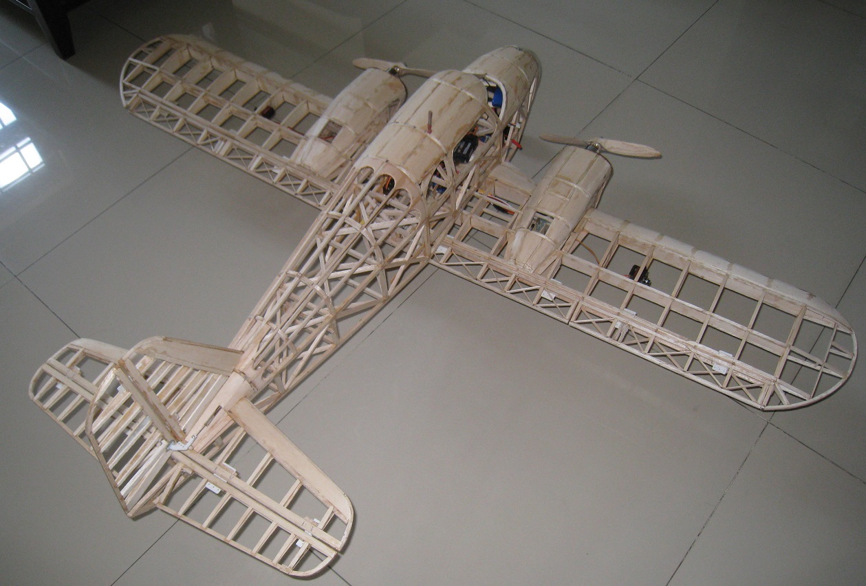
Wing : Was an 448
square inch and all wooden contructional wing .The
wing- airfoil is NACA 3413 ..and is one
piece detachable wing . Dehydral angle is 3 degree and
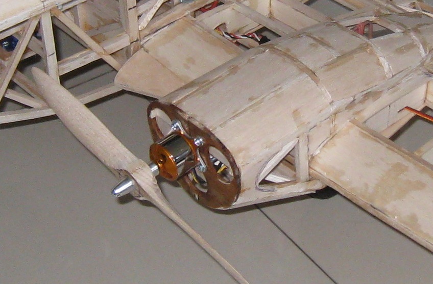
attack angle was 1,5 degree . I used two brhusless motor
2200kv A2212 attached with the wing motor mouch and fixed by
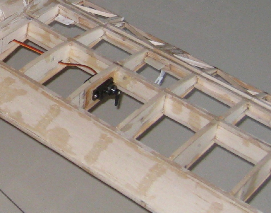
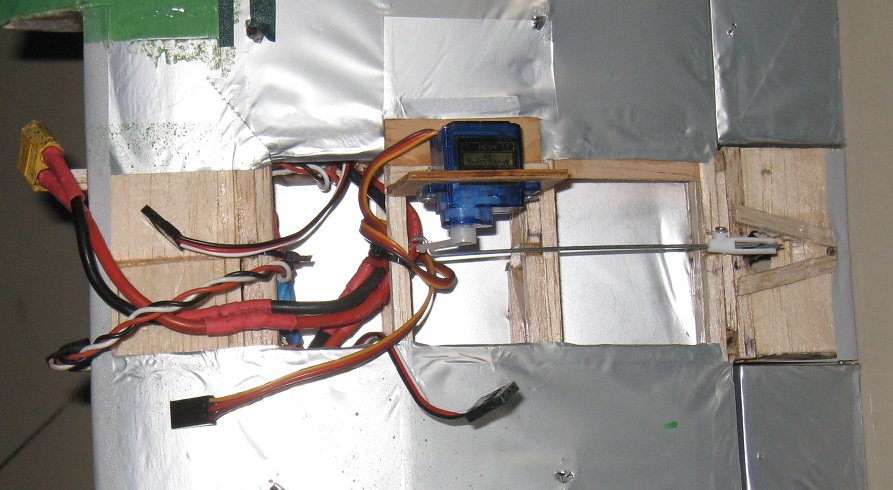
four screw installe on the wing ( see pic ) . The two aileron system
( see pigures ) .are independable , each is control by one 1,2 Kg
miniservos , installed hide into the wing .The hinges of the
aileron are three piece plastic hinge and installed at the
middle of the rear wing bar . The right and left flap are simutanement
control by an simple metalic transmission and control by only
one servos ( see pic ) All the wing covered by silver color PVC
and attached to the fuselage by 5 screw
|
|
|
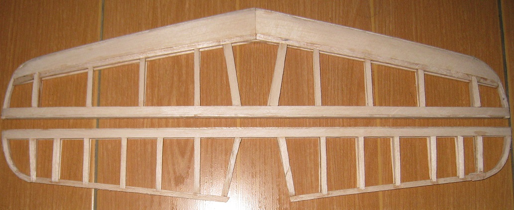
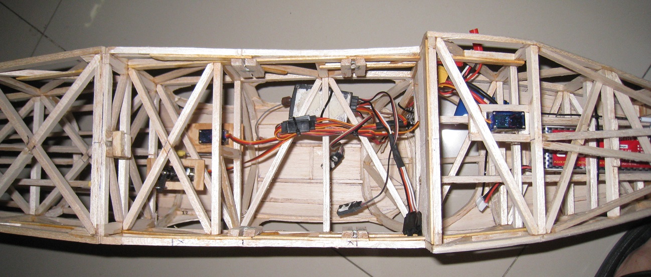
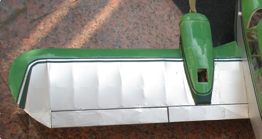
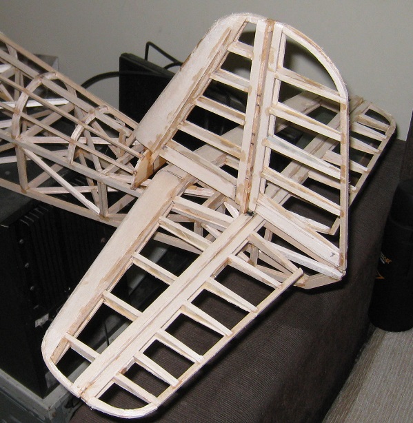
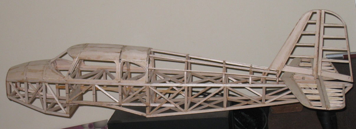
| Fuselage and stabilizer :The
main contruction of the fuselage is all wooden air-frame with
four main bar balsa wood 4mm x 6mm ( see plan ) .The
desk and the upper of fuselage was renfoced by hard plywood
The stabilizer elevator and rudder was standing on the right
angle . . . |
|
|
 |
.
 |
| |
 |
|
 The attachement of the wing to the
fuselage is two .19 and .16 alluminum rod tube
placed in front and rear and fixed easily by six
screw in the fuselage |
|
| |
|
|
|
|
|
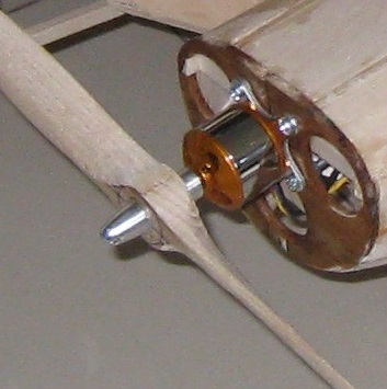
| Engine and propeller : The
two engine in used are brushless motor A2212 2200kv . The engine standing
on hard 4mm plywood deck , fixed by four screw ( see pic ),
ESC are two 40A each with Bec 5v , 3A , Down 1
to 1.5 degree of the engine axis
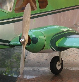
are require .The styrofoam canopy covered by
green PVC on
the front let to see very good form and
firm mouting (see pic ) . I
used two right and left wooden handmade propeller to prevent the
anti-torsion of the engine . The propeller size are 8x6 , its
work best on 14.000rpm with 3s battery
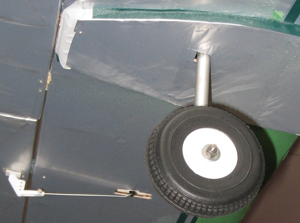
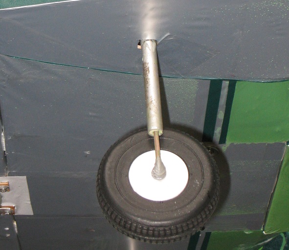
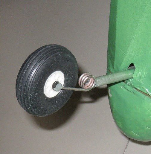
Gear system : Three 6mm aluminium tube with 3mm sprintable
steel rod get this airplane on good see sprintable gear have an sweet and safe
landing ( see pic ) . The front gear are dirigeble and sprintable
.
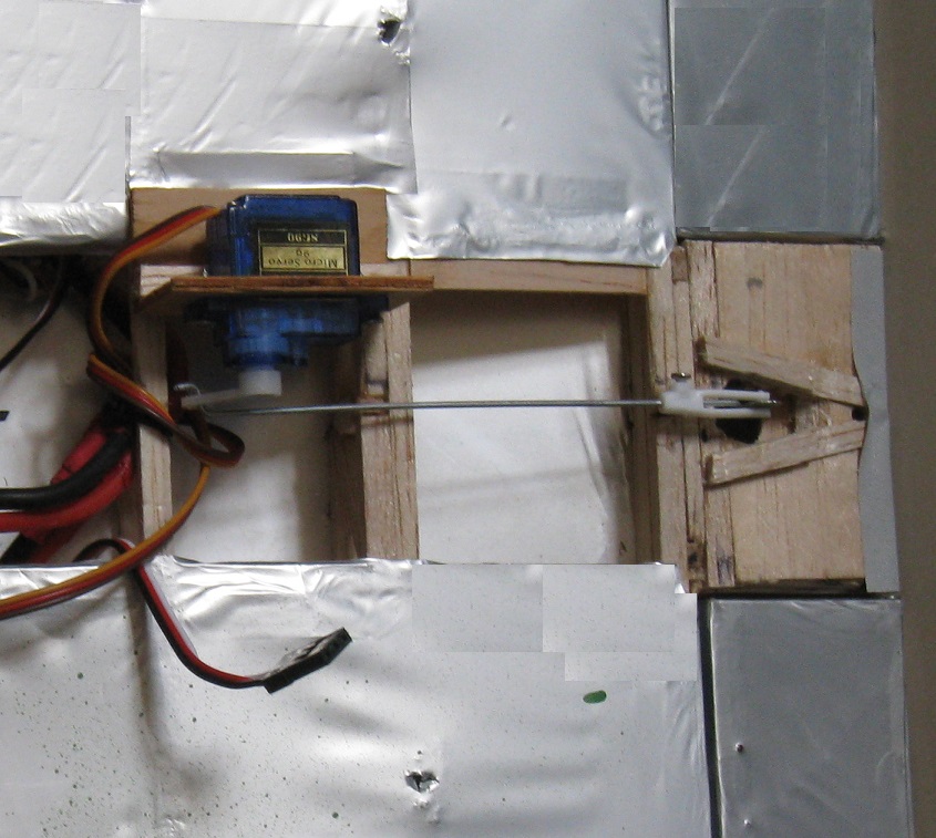
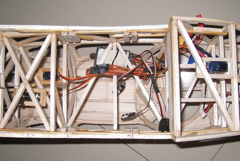
R/C system , servo & other link installation :
Three 1,5kg mini servo for elevator , aileron & three 1,5kg servo
for rudder , dirigable front gear and flap . The
battery are
fixed in front on the lower of the fuselage and adjust for the CG (
Center of gravity ) at 27%-28% from the front edge of the wing cross section
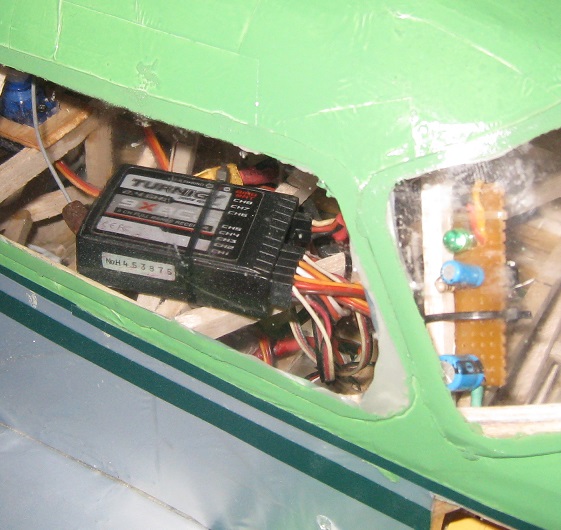
. I used one IC 7805 to build an second electronic Bec supply by
7,4 v battery to
prevent the lack of current supply for the control systeme when
you have an overload fly ( sea pic ) . The receiver
was place on the highest of the fuselage nearby the CG
and sticking on the base of a rubber foam-sheet for reduce the shock . |
| |
|
|
|
| |
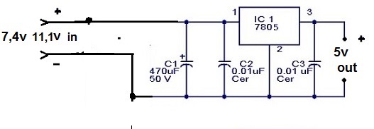 |
I used the IC 7805 to
build an second Bec electronic tranformer to reduce the battery
voltage from 7,4v -11,1v to 5 volt , 3A , ( see schema)
this connect to the battery pin on receiver . This systeme
will be prevent the drop voltage supply for receiver when
we fly overload ( see pic ) |
|
|
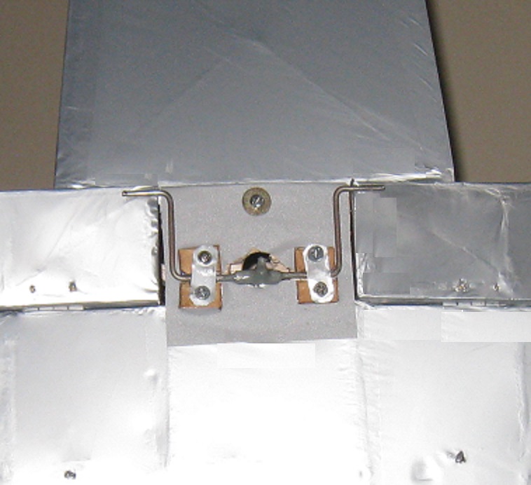
| The rudder and elevator's rod
are two 2/8 carbone rod tube with two 2/32 steel wire fixed
at the end ( see pic ) . These are light , hard and had
any trouble in working Rudder , elevator , aileron adjust & flying test : Up
1/3 inch and down 1/4 inch for elevator . Right 1/3 and lelf
1/3 for
rudder and 1/4 inch for the aileron . On the first fly ,
reduce some in the angle-effect for the aileron an elevator
and slight trim down on elevator , on the first test flight ).
|
|
|
|
|
|
| On a
clear and calm sunday morning , I made my first flying test ...... |
|
Click
to see the
character and outdoor images |
 _______ ____________Back
to main page _______ ____________Back
to main page |
|
-My
home page I My
family home page I My
personal page I Medline
IR/C model airplane page
I Games
I Science
|
| Add :
Dr BUI BINH THO 35B Ho Hoa , To1 , Kp 1 , Tan Phong ,BIEN HOA , DONG NAI
, VIET NAM Email
:
buibinhtho52@gmail.com
Copyright
© 2001: My homepage's Bui Binh Tho Md
, 35BHo Hoa, to1, Kp1, Tan Phong , BIEN HOA , DONG NAI , VIET NAM . Tel (0251) 8820217 ,
Mobile : 0903358597 . Plus ( +84 ) for all oversea relation .
All
Rights Reserved.
This document is strictly for informational, non-commercial purposes.
|
|








 _______ ___________