R/C
Model airplane
page  |
 |
| |
|
|
| ______________________________________________________________________
BUI
BINH THO MD
__- |
|
|
|
R/CModel airplanepage My
Super De Havilland Beaver |
|
Crete : 12 Aout 2023 |
 |
|
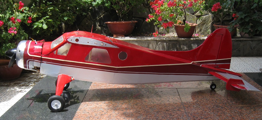
Super
Dehavilland Beaver
| Wingspan
: 83.5 inch ( 2100mm ) |
| Length
: 56 inch |
|
High wing air foil NACA 3412 |
| Weight
: 10 lbs ( 5kg ) |
| Engine : 91-
108 Two
cycle Nitro engine or 15-20cc gas engine |
| Contruction :
All wood air frame & thin layer silver PVC covered |
| Radio :
5 channel |
|
|
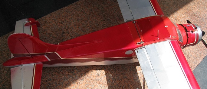
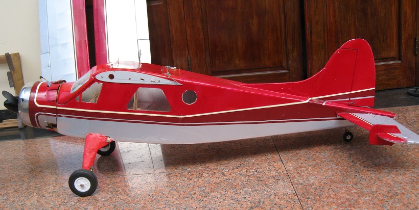
| After
the pandemicCovid 2022 I decided to build an big high wing model
airplane the Dehavilland Beaver , the most used aircraft in
North American an Canada . I used the Dehavilland Beaver
3D viewn plan with some modified on the wing span and the horrizontal
stabilizer . More light , strong material had
been used to contruct
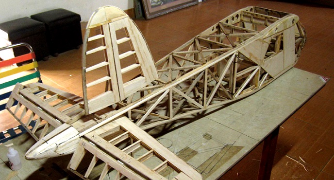
this model airplane ;but the balsa wood is usually the good materiel to
made its . The contruction of this aiplane is all balsa wooden
air-frame renforced by hard wood; covered by thin
light silver PVC . I thing this is the one in most big scale
wooden R/C model airplane which I was
doing ( try on ! ) .
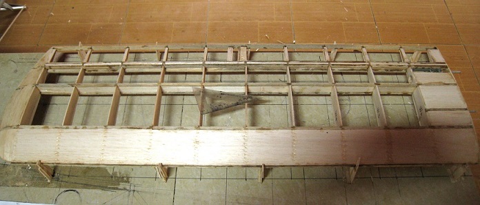
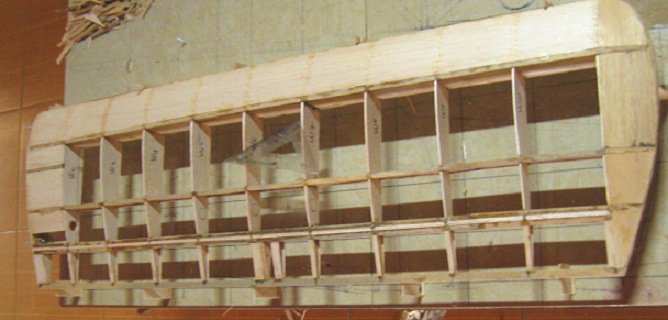
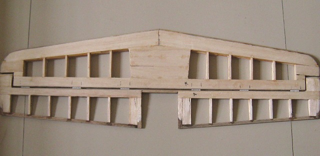
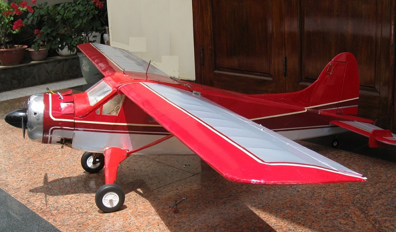
Wing : Was an 920
square inch and all wooden contructional wing .The
wing- airfoil is NACA 3412 ..and have two
piece detachable wing . Dehydral angle is 3 degree and
attack angle was 1,5 degree . I used two .19 and .16 aluminium
tube attached with the fuselage and fixed by six screw installe inside the
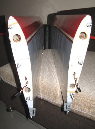
fuselage . The two aileron system
( see pigures ) .are independable , each is control by one 9Kg
servos , installed hide into the wing .The hinges of the aileron are three piece
plastic hinge and installed at the middle of the rear wing bar .
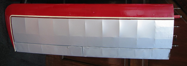
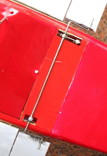
More hole in the wing foil lamina was reduce more the total
weight of the wing . The right and left flap are simutanement
control by an simple metalic transmission and control by oly
one servos ( see pic ) All the wing covered by silver color PVC
|
|
|
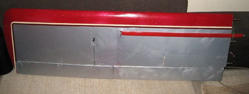
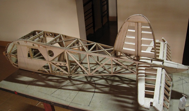
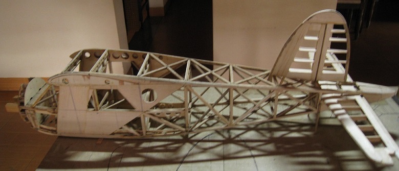
| Fuselage and stabilizer :The
main contruction of the fuselage is all wooden air-frame with
fourt main bar balsa wood12mm x 12mm ( see plan ) .The
desk and the upper of fuselage was renfoced by hard plywood
The stabilizer elevator and rudder was standing on the right
angle , two small vertical stabilizer are in place on , near the
external tip of the elevator . . . |
|
|
 |
.
 |
| |
 |
|
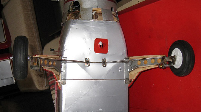
The attachement of the wing to the
fuselage is two .19 and .16 alluminum rod tube
placed in front and rear and fixed easily by six
screw in the fuselage |
|
| |
|
|
|
|
|
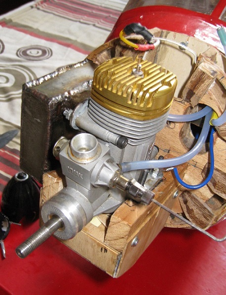
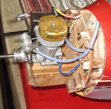
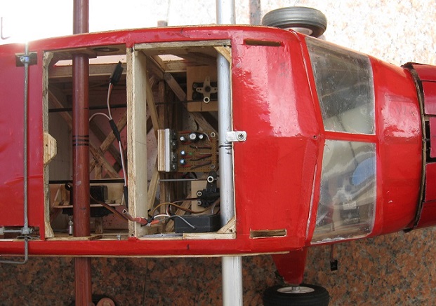
| Engine : The
standing of nitro engine is alumium standing engine or hard wood
standing deck fixed on two layer of plywood ( see pic ). Down 2
to 2.5 degree and 1,5-1,7 degree to the right of the engine axis
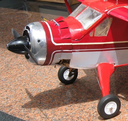
are require .The fiberglass canopy with alunium on
the front and fiber composite at the rear and had wide
sufficement iopening in air intake , given a very good form and
firm mouting (see pic ) .You can
use the engine from .91-.108. i used the .91 Vmax nitro engine . To augmente the power of this
engine , I change the standard muffler by an new two exhaust
tube muffler , and by this I can change the normal 13x6 by the
14x6 propeller which this has any trouble
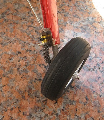
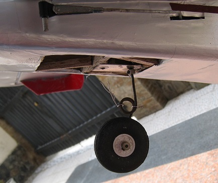
Gear system : Two 2,5x 1cm stell rod and sprintable
stell rod get this airplane on good see and have an sweet and safe
landing ( see pic ) . The rear gear are dirigeble and srintable
.
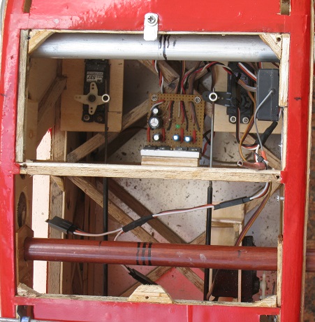
R/C system , servo & other link installation :
Three 9kg-servo for elevator , aileron & two 3,5kg servo
for throttle-valve and flap .
An 6,5kg servo was using for rudder and tail wheel . The
battery are
fixed in front on the lower of the fuselage and adjust for the CG (
Center of gravity ) at 29%-30% from the front edge of the wing cross section
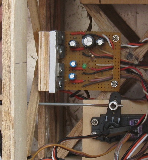
. I used four IC 7806 to build an electronic tranformer to
reduce the battery voltage from 11,1v to 6 volt , seperate on
four Bec : 6v ,5A output on each Bec( see schema ) . The receiver
was place on the highest of the fuselage nearby the CG
and sticking on the base of a rubber foam-sheet for reduce the vibration of
engine and the shock . |
| |
|
|
|
| |
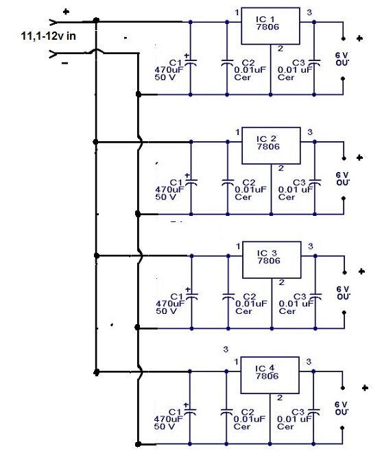 |
I used four IC 7806 to
build an electronic tranformer to reduce the battery
voltage from 11,1v to 6 volt , seperate on four Bec
: output on each Bec is 6v , 5A ( see schema) . Three in four Bec are supply to three 9kg servo , this systeme
will be prevent voltage drop when all servo operate
simutaneously |
|
|
| The rudder and elevator's rod
are two 2/8 carbone rod tube with two 2/32 steel wire fixed
at the end ( see pic ) . These are light , hard and had
any trouble in working Rudder , elevator , aileron adjust & flying test : Up
2/3 inch and down 1/2 inch for elevator . Right 3/4 and lelf 3/4 for
rudder and 1/2 inch for the aileron . On the first fly ,
reduce some in the angle-effect for the aileron an elevator
and slight trim down on elevator ( on the first test flight ).
|
|
|
| On a
clear and calm sunday morning , I made my first flying test ...... |
|
Click
to see the
character and outdoor images |
 _______ ____________Back
to main page _______ ____________Back
to main page |
|
|
|
-My
home page I My
family home page I My
personal page I Medline
IR/C model airplane page
I Games
I Science
|
| Add :
Dr BUI BINH THO 35B Ho Hoa , To1 , Kp 1 , Tan Phong ,BIEN HOA , DONG NAI
, VIET NAM Email
:
buibinhtho52@gmail.com
Copyright
© 2001: My homepage's Bui Binh Tho Md
, 35BHo Hoa, to1, Kp1, Tan Phong , BIEN HOA , DONG NAI , VIET NAM . Tel (0251) 8820217 ,
Mobile : 0903358597 . Plus ( +84 ) for all oversea relation .
All
Rights Reserved.
This document is strictly for informational, non-commercial purposes.
|
|